WINISO® 3D
Calculation of heat flows,
2D and 3D thermal bridges, isothermal surfaces
and U-values according to EN ISO 10211
Professional calculation
U, Ψ, X, isotherms, mold and condensation risk
Powerful functionality
for the thermal calculation of windows and facades
Imported 3D CAD data can be intuitively and efficiently cleaned of errors and prepared. The essential details can be worked out specifically and true to the original from extensive and complex source data. After simple processing and a short calculation time, the FEM calculation kernel delivers the thermal properties of the detail with maximum accuracy.
Performance features
- Highly automated geometry preparation of CAD data (DXF, DWG, STEP)
- Detailed transfer of CAD data. Recognition of curved surfaces (radii, freeform) Automatic and manual preparation
- FEM calculation with flexible automatic tetrahedron meshing. Automatic mesh refinement on small-scale geometry details
Try our demo version!
Why WINISO® 3D?

- Certified by independent testing institutes
- Results are internationally recognized
- Extremely user-friendly operation
- Reliable partner for long-term customer satisfaction
- Market-ready solutions even before the relevant laws and standards are passed, along with ongoing updates - our solutions are always up to date
Short presentation
Examples
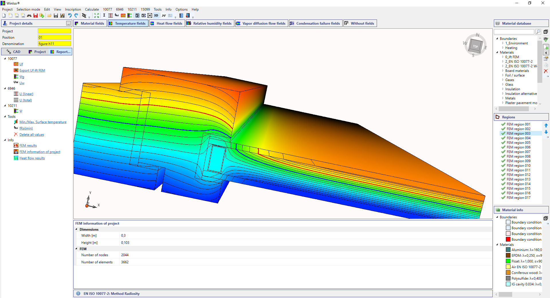
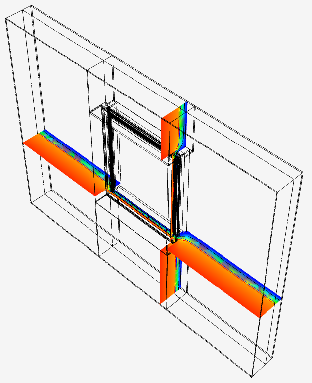
Wall connection: Wooden window in external wall/WDVS
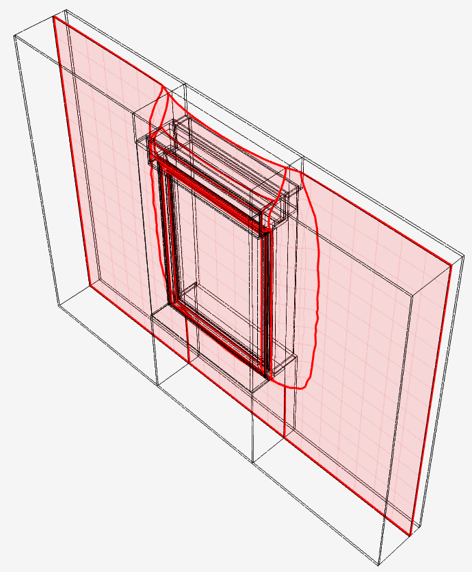
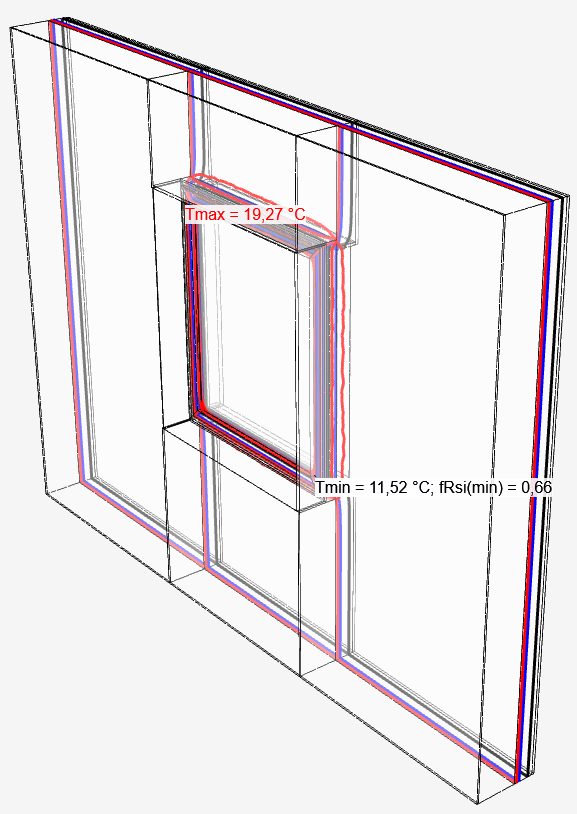
Determination of isotherms and minimum surface temperature on the inside of a window in the specific installation situation.
Roller shutter box
Roller shutter box according to DIN 4108 Bbl. 2 – Old building variant and thermally optimized design. Minimizes the thermal bridge and eliminates the risk of mould and condensation.
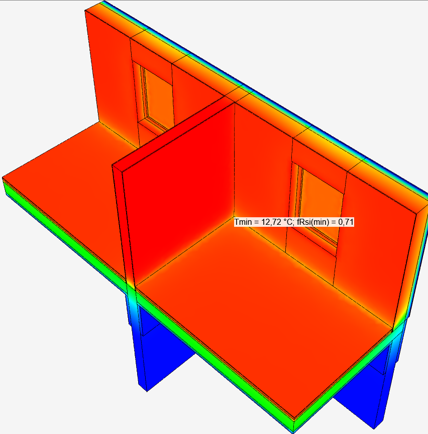
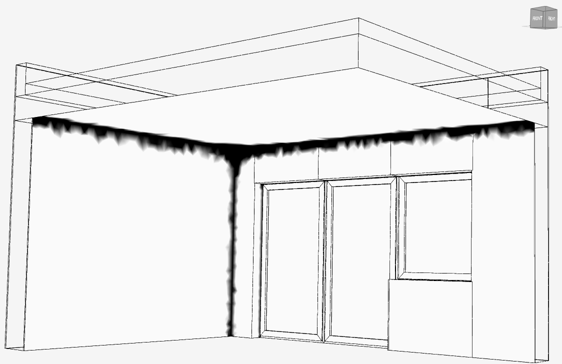
Parapet – three-dimensional thermal bridge in the corner of a room
Unrenovated condition and renovated with ETICS. Clear illustration of the risk of condensation (100% humidity) and elimination through optimized insulation design.
CAD
CAD import and cleanup
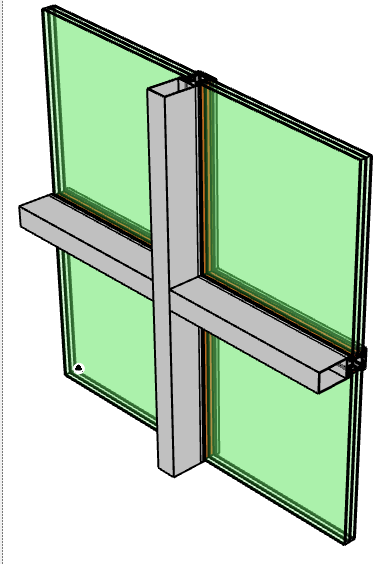
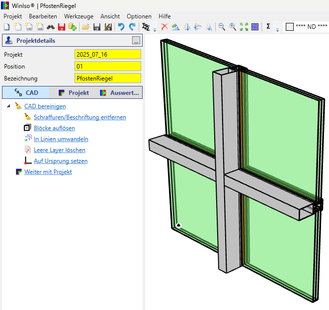
WINISO® 3D imports CAD data as DWG, DXF and STEP. Efficient tools for CAD preparation create a seamless transition from CAD to FEM during data transfer.
During CAD import, WINISO® 3D efficiently extracts the essential properties for the simulation from the extensive details of a CAD drawing. Unnecessary information such as hatching, labels and dimensions are automatically removed and the geometric properties are converted into a clean, consistent and unambiguous line geometry. The bridge between CAD and FEM simulation is thus simple and intuitive in WINISO® 3D.
Create 3D body
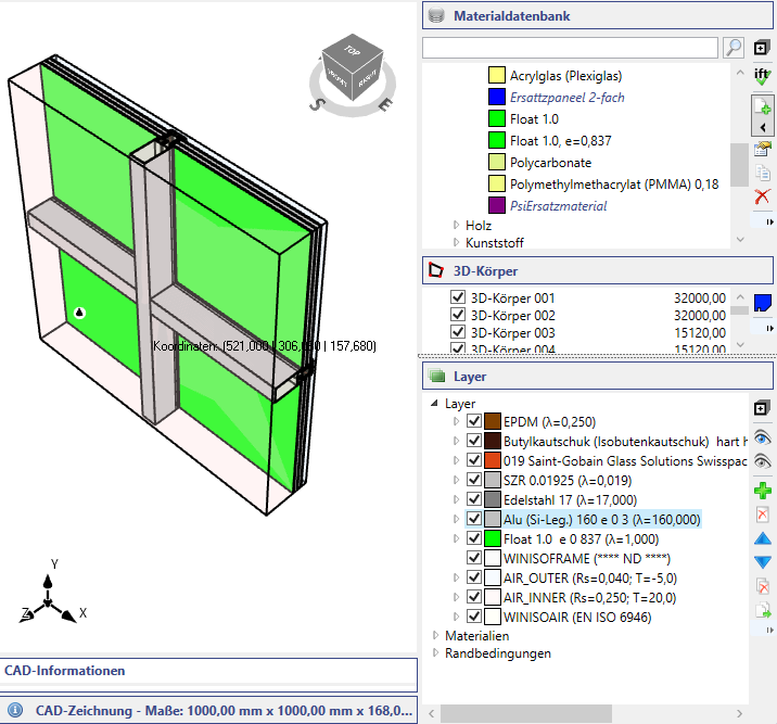
When creating and editing the 3D geometry, the essential features and contours of the design are obtained and the foundation for an efficient and fast FEM calculation is laid.
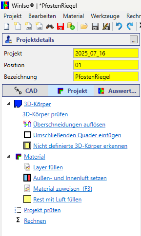
3D bodies are automatically recognized from the prepared CAD geometry. They form the basis for an efficient and fast FEM calculation mesh. A powerful set of tools supports the WINISO® 3D user in recognizing, checking, cleaning up and simplifying the 3D CAD geometry. The characteristic features of the design are thus worked out and important CAD properties such as material assignments are automatically adopted.
Tools
The imported CAD data can be easily and flexibly edited and supplemented with an extensive set of CAD tools.
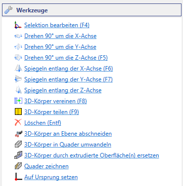
There is no need to use CAD software to make changes to the CAD data – WINISO® provides a coordinated set of tools for adding to and adapting the CAD design. In addition to the standard functions such as copying, pasting, rotating and mirroring, 3D objects can be trimmed, combined and reconstructed.
Project editing
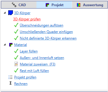
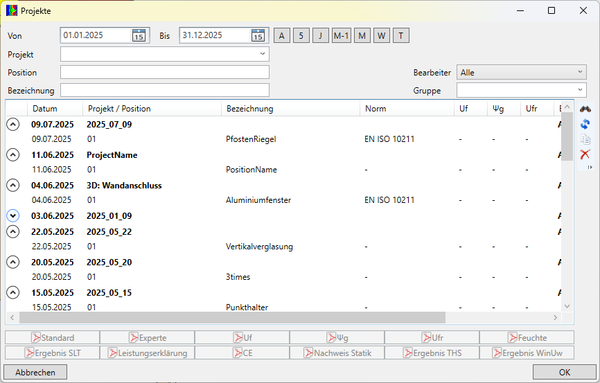
Create and edit your simulation projects intuitively, quickly and accurately with the coordinated tool set of WINISO® 3D.
Edit 3D body
The imported 3D geometry can be adjusted with intuitive editing functions for cropping, rotating and positioning. Complex geometries can be reproduced and handled by replacing them as cuboids or extruding surfaces.
Material assignment
Materials can be automatically assigned manually to layers according to layer name or created assignment.
WINISO® 3D offers an extensive material database; materials defined by the user are saved in the SommerGlobal® database and are available for all subsequent projects.
Evaluation
Standard-compliant, automated, intuitively understandable and freely configurable – the WINISO® 3D evaluation and report tools provide you with targeted support in generating and presenting your calculation results.
Temperatures
In the result display
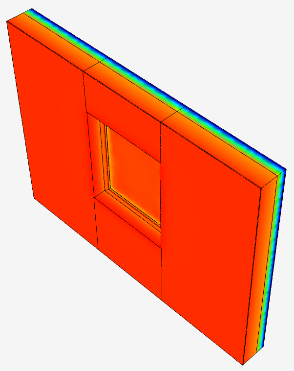
Temperatures in false color representation
either on the component surfaces or on sectional planes through the component.
Isotherms
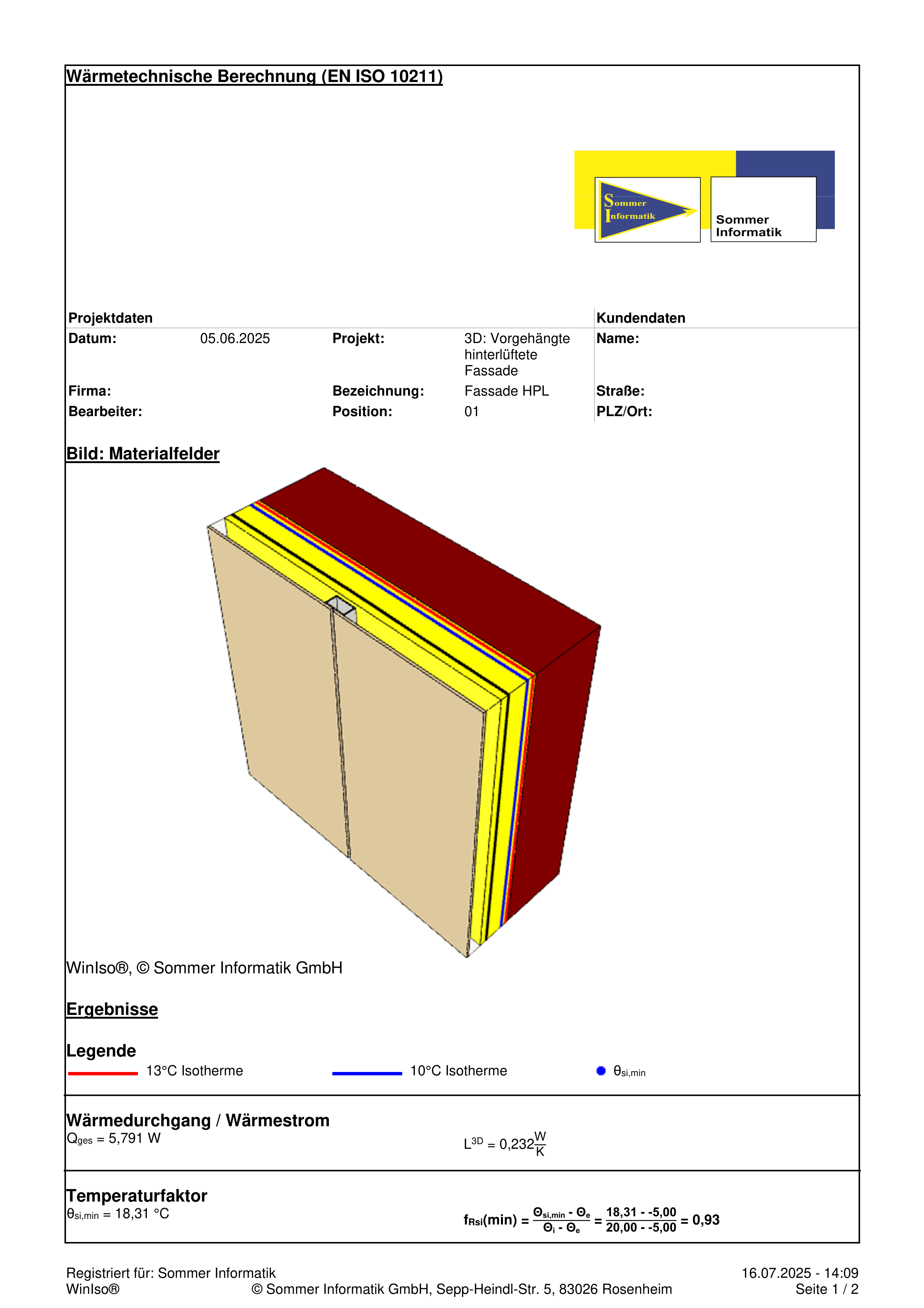
Isothermal lines can be shown in the results display to visualize the progression of critical temperatures in the construction. By default, the isotherms 13°C (risk of mold), 10°C (risk of condensation) and 0°C (frost) are displayed. The isotherm display is freely configurable.
Thermal bridges
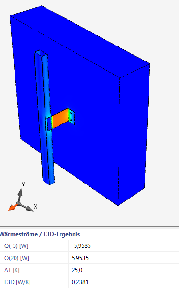
By evaluating the three-dimensional thermal conductance L3D and simple variant calculations, point thermal bridges χ can be quantified.
Present
The “Standard” and “Expert” report templates can be used to create printouts and PDFs with the relevant representations and characteristic values. Reports in Word format can then be further customized and supplemented.

